2022-06-27

That Fkn Donut

I made The Donut, apologies in advance. Thanks to Blender Guru for his tutorials. Want a mind-bending rubix-cube type project to stave off dementia? This one is highly recommended.

https://www.youtube.com/watch?v=nIoXOplUvAw&list=PLjEaoINr3zgFX8ZsChQVQsuDSjEqdWMAD


My two innovations are:

  1. Hard candy spheres FTW
  2. The green sphere got lost in the donut hole shadow so i put a 1 milliwatt light inside it to make it sparkle a bit


2021-07-02

Building a POT Clone Guitar Pedal Based on the PedalPBC Pauper Schematic - Part the Bth

I spent about 3 hours debugging, which is actually better than I had any right to expect. There were 3 missing solder joints in the wire superhell on the back of the perfboard. 

Assembly Gutshot

 Here's the guts installed in the enclosure. Mocking it up on the cardboard probably made the difference between success and me throwing this whole thing across the room in disgust.


All Soldered Up 

Here's everything all together. I mean, I gotta admit it worked out:
  • The in/out jacks clear the tops of the side switches
  • The in/out jacks don't stop the cover from seating
  • The DC jack, although it's a 3-connector type, does clear the center mode switch


Assembled

Here's the best possible viewing angle for this thing. From here you can't see the controls are all misaligned, though you can see the (LOL) washers I had to put on the DC jack (LOL) because I drilled the hole too big with my brand new step bit. Love that thing though.


And now here it is next to my first pedal, a clone of a Colorsound one knob fuzz (it has a bonus input sensitivity knob).

Sound

It's anybody's guess whether I really got this correct. Are all the component values actually right? Did I mess up something in one of the feedback loops? Who can say? But it sounds nice. I'm not sure I can really tell if the mids and turbo switches are working, or even if I have them labeled backwards. 

But it sounds like...an overdrive. I don't even like overdrives except in front of distortion. I think if I had to choose between this blues breaker-style pedal, and a screamer-style pedal, for use in front of an regular (not high gain) amp, I'd pick this one. It seems to have less of that screamer crackle haze in the top end.

2021-06-15

Building a POT Clone Guitar Pedal Based on the PedalPBC Pauper Schematic - Part 1

References: 

  • PedalPCB Pauper build docs here: https://www.pedalpcb.com/product/pauper
  • I get most of my parts from Small Bear:http://smallbear-electronics.mybigcommerce.com
  • I don't need another overdrive. I already have a Strymon Sunset I'm pretty comfortable with, so I don't know why I'm doing this.

Perfboard Layout

I've already perfboarded a clone of the Colorsound one knob fuzz, so I felt ready. Was I wrong. The layout for this took me literally 20 hours, I’m not kidding. Drawing, erasing and redrawing to the point of nausea. Felt 10x harder than the little fuzz. It was a learning experience, and I will do better next time, but holy crap. The feedback loops around gain stage one were hard to map, and the output tone section was eye opening - look at those weird little loopy bits on the right side. This is a particular flavor of mental effort that I've never tried before - nothing in my life had prepared me for it. 

Managing to put VREF (1/2 rail) in the places it was most needed was interesting. I couldn't get it from the pots to pin 5 of the op amp, so down below in the rear perfboard image you'll see little wires everywhere. In this layout, little wires are be required for:

  • Tag A, going from stage one to stage 2
  • Tag B, going from stage 2, to one side of the clipping section, and on to the tone section
  • The VREF to the IC, as mentioned above
  • Ground to the IC, and to the input common

Perfboard Solderjob (Front)

Note that my layout failed to account for the large size of the 100uf electrolytics, as well as the 1uf poly caps. The layout assumes that all resistors are loaded vertically and take just two adjacent holes, and that all caps take 3 adjacent holes - neither having much width. So you'll see my optimistic layout sprawls quite a bit when I got to the supply filtering (C10, C11).

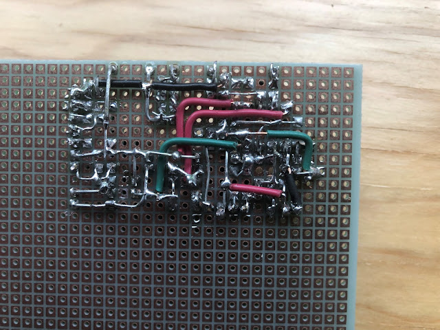
Perfboard Solderjob (Rear)

The solder side of the perfboard is a two layer wire superhell. I've seen other boards where people sort of draw traces on the pads, bridging them together in relatively neat lines. Haha lame! I solder the components in, then I bend all the wires over to touch each other. I used thicker leads from some weird old power resisters for the posts, and bridge the components to those. I'm not proud of it.

Control Layout (Front)

This is the what the front might look like. I'll do all the wiring on this jig so I don't have to work in a 125B enclosure. I'm bringing the dual gang DIP and internal treble trimmer out to the front, like a daft nutter. The only thing I'll have to solder when it goes into the real enclosure is the DC jack, which unfortunately has an internal nut.

Control Layout (Rear)

Here I've trimmed the board on a band saw with a metal cutting blade, so it fits easily in the 125B. All the jacks will go at the top (in/out/power). I've calculated that, in a perfect world, the plastic 1/4" box jacks will ride a couple of millimeters over the terminals of the left and right switches, while the 2-terminal power jack will clear the top of the center switch housing by a similar amount. My pedal calculations are often wrong. Yes, the left and right (canonically DIP) switches are SPDT here, which is an extra throw, but if this pedal doesn't work out, then...SPDTs are more versatile and cost very little more.


The plan is to wire up just the potentiometers and test. All of the switches have a default off position, so leaving them unconnected should put the Pauper/POT in "boost" mode for the first test.

I give this a 50% chance of being an undebuggable nightmare that I have to scrap in defeat. Witness me.


2020-05-16

A Problem with The Mixer Control on My USB Audio Interface Made Me Think All Guitar Impulse Responses Sound Bad

For over a year I thought something was wrong with my guitar cab IRs when I played direct into my DAW. My setup is a bunch of pedals going into my audio interface like this:

IR Loader in DAW <-- USB Interface <-- High Gain Pedal <-- Boost Pedal <-- Tuner <-- Guitar

Yes, I play with no power amp, real or simulated, although I'm told a tube power amp is used to generate most guitar cab IRs, so maybe I get some tube sauce for free there.

Symptoms

  • IRs sounded like they had too much room sound. As if they had a small ambient room reverb on them. Like how I'd imagine it would sound if you mic'd an amp from too far back. You do you, but for high gain I want my mic'd sound pretty dry.
  • Sometimes my high gain tones sounded spitty and gross. I couldn't dial out the fizz and crackle without losing the whole top end. Sometimes it verged on unplayable.
  • One week or one session things sounded great, the next week I thought I was crazy to like that sound. That's normal for me, where one day I think a tone is perfect and then next I dislike it, but this was nuts.
  • I thought I was going crazy.
  • I thought...maybe IRs are overhyped bullshit?
  • I thought...maybe there is something wrong with my pedals?
  • Then the other day I suddenly realized that I could not get the sound in my phones to sound like the sound that was recorded in the DAW. This should not be the case ever. I was supposed to be hearing 100% DAW playback sound from my interface, in both my phones and speakers - the same sound that is recorded in bits and bytes.

Cause

  • The mixer knob on my audio interface had always let a tiny bit of direct sound into my phones/speakers, even when I had it turned all the way to "Playback". I knew this all along, but I didn't think about it, because I am a dumbass.
  • The way I knew this was: with the guitar track record button turned off in the DAW, if I turned my phones up loud I'd hear a bit of high gain junk when I played. It sounded like an industrial guitar track. I figured, that's weird...but how much can it hurt?
  • A lot. It can hurt a lot. It can make you think that IRs are stupid, when the entire rest of the world seems to like them a lot.
  • This was especially apparent when I had my DAW session really quiet, which happens sometimes because I'm shit at gain staging, and I forget things. When that happens, I have to turn up my phones or speakers to compensate, and the proportion of direct sound to DAW playback sound would go up. It turns out that those were the really bad days.

Approaches

  1. Live with it. Gain stage my projects so that the proportion of fizzy direct sound is as small as it can be compared to the project level. Probably a good idea anyway? You tell me, but probably.
  2. Get a new audio interface and hope it didn't happen there. My current audio interface is very low end, and out of production, so I figured what are the chances this happens again? This probably would have been a good approach.
  3. Hack up my current audio interface with a soldering iron.

Solution

I chose approach I nearly always take: hack shit up with a soldering iron. I don't recommend this unless you know what you're doing, and are ready to replace your hardware if you break it. I came so close to breaking mine.
  1. I took the interface apart. Lots of screws holding in the mic/instrument combo jacks and MIDI connectors, nuts holding in the pots and 1/4" jacks, and a single riser board for the top set of pots. This part was easy and fun.
  2. I located the stereo B10K pot, and discovered it is a standard voltage divider. If you don't know what one of those is, you can stop now. I sorta know what a voltage divider is. That gave me incorrect levels of confidence.
  3. Turned it all the way up to "Playback" and found it was 1.6 ohms on one set of legs, and 10K on the other. Voltage divider? I decided it is. What else could it be, it's a mixer pot? Right? I'm probably wrong.
  4. Got the pot off the board. What a nightmare. I am terrible at desoldering parts that have more than a couple of legs. My solder sucker is half broken, the tip is all melted and fuzzy, I can never get solder wick to work, my hands are shaky, and I'm just terrible at this. I ended up literally destroying the pot with a pair of nippers and pulling the chunks of plastic off the board, leaving only the legs. I was able to get the legs out by applying heat and pulling with the needle nose pliers. I mostly didn't scrape any board traces by accident. Mostly.
  5. I soldered the 1.6ohm set of through holes to short them out using clipped off leads from an old resistor, and left the 10K stereo set open.
  6. Apparently I didn't cut any traces or chip any important surface mount resistors.

Results

  • Now, when I have my DAW record button off, and my monitor level all the way up, and playback is stopped, and I hit the guitar strings, I hear literally nothing in the phones or speaker. You obviously want to watch your ears doing this, and make sure you turn in back down fast.
  • My IR setup sounds the way I imagined it should - very dry, no fake "room sound" effect.
  • My guitar tone sounds the way I imagine it should - no industrial guitar fizz, unless I put it there on purpose.
  • I feel stupid, but I'm recovering slowly.
  • I didn't get an excuse to buy a new audio interface, which is a bummer because I am am a monkey that likes shiny new things, but good because the fun wears off on those even quicker than most gear.


2014-11-23

Built my own vocoder in Reaper DAW - For No Reason

This is a seriously backwards project. It's built in Reaper using only stock plugins. Keep in mind the important fact that I am not a genius. There are probably a hundred better ways to do this just in Reaper, and there are probably 10,000 better ways to do it in an audio programming language. People build these with analog electronics, too, but those are pretty high on the parts count. I wanted to spend a nice day off on this, not a terrifying rest of my life.

An interesting but incorrect fact: the Wikipedia article on the Vocoder says it was invented to compress and more easily encrypt voice transmissions, which is obviously wrong! It's clearly used for making robot sounds.

To download a zip of the full Reaper project, click here. Here is what the project looks like:

Here's the output from my Reaper vocoder: https://soundcloud.com/superbonuspak/reaper-daw-diy-vocoder-experiment-1

And here's how I think it works:
  1. Mod Generator is the voice that will modulate the noise. I called it that because originally I used the JS: synthesis/tonegenerator to sweep my frequency bands, before I replaced it with my voice. The sends go prefader from here to each of the Bandpass X tracks - prefader so that you can turn it down (don't want to hear myself dry) but it still goes to the sends. This has a copy of me on it saying something.
  2. Noise Generator is the sound to be modulated. I called it that because originally I used pink noise. That still works fine. You can replace the ReaSynth on that track with the JS: Liteon/pinknoisegen and you'll get something that sounds less musical, and slightly more voice-like. Ha ha not really. But less musical.
  3. Bandpass X (where X is a number from -1 to 5). This simply receives the Mod Generator voice and bandpasses it way narrow using ReaFir. Each band (each X) is a different notch in the spectrum, from about 300hz to 1500hz.  Why that range? Because I got tired of making bands. Why is there a band -1 and 0? Because after I did band 1-5 I realized I wanted to go lower, and I didn't want to redo all the filters. I just couldn't face it. Like Mod Generator, these are also pre-fader so it can be turned down all the way but still do the sends.
  4. Noisemod X uses the Bandpass X send as sidechain input to a JS: SStillwell/expander. The noise comes in from the Noise Generator track via prefader sends, it is filtered with an exact copy of the ReaFir bandpass from its associated Bandpass X, and then goes into the expander, where the output from Bandpass X is sidechained in on 3/4. The expander has a high ratio and carefully tweaked threshold. These are the only tracks that are allowed to make any noise.
This is obviously not a practical way to build a vocoder, but I did learn some of the basics. I think it says something good about Reaper, that it's got the routing mojo to handle this. And I may use Reaper to explore more basic synthesis ideas in the future - it's almost like a bunch of little modules that can be connected by wires, very inexpensively.


2013-05-26

Raised Bed Garden with Integral Fence and Access Doors

This is my raised bed vegetable garden, designed to keep out nature's little Dr. Lecters. We have a herd of deer, a gang of woodchucks, a squirrel riot and a insurgent army of chipmunks that will fight a dog over a bone. I don't know if this will work or not, but it's a try. Check it out, the sides open on hinges:
Eye hooks with bungee cords hold the doors closed, necessary because this thing is built to such loose tolerances that I am ashamed. I guess the idea was (there was an idea) that it would be easily disassembled and loosely coupled so it would go pretty much anywhere and hang together. In that respect I guess I succeeded. I guess.
It started as a box of 1x12 #3 cedar, 8 feet by 4 feet (or so). It was important to keep the long side exactly 8 feet because so much of the wood is on those sides, so the short sides are butted in between the long sides and cut a couple of inches shorter so that half-lengths would span it. The mesh is 1/2" galvanized 19 gauge "hardware cloth". It doesn't remind me of hardware and it's nothing like cloth but what can you do - that's what they call it. This is the floor that stops the woodchuck from digging up through the bottom.
I leveled it in the yard somewhat, but not completely. That's important, because I should have leveled it perfectly. Why did I not? Well, why do I do anything? For some reason on the day I was doing this I decided it was good enough, not really thinking through the concept of swinging doors that would want to be level, and how that would match an off-kilter base. I think it's because I was facing the task of dumping 1.2 yards of topsoil into this with a wheelbarrow and a car ramp, and I got everything all mixed together in my head.
There you go, almost ready for dirt.No, wait, don't do it! What if I filled it up now and then I want to drive my U-posts into the corners and they hit a big rock and I had to dig the whole corner out? Or, worse, move the whole frame because the rock was too big? First I need to put in the posts.
Posts and dirt. I bent the flanges on the posts because I want them to go right into the corners.
That's a good one. It looks great. The face of the post is right up against the box corner so that when I face the U-post with a 1x3 cedar plank the bottom of the plank will be flush with the wood of the box, and therefore the door will close with no gaps. Sounds great but the fact is that this post is not completely vertical, so when I goof around with it to get it more vertical it will open up a gap down there. But probably no bigger than the 1/2" of the fence I'll be using.
A door. 4 by 8, the reason I fought to make sure the box was exactly 8 feet long all the time. So I wouldn't have to cut those long boards at all. The verticals are just a 1x3 cut in half.
Fastened with stainless wood screws. The long end is going up to the left.
Then a strip of 1x2 cedar is used to make the short sides flush, plus secure the mesh as well and hide the bitter nasty cut ends from the door user.
In my imagination this board would be flush with the face of the box. Imagination is a wonderful thing, but actual thinking would be better.This is a 1x3 board bolted to a U-post in the corner. That's the reason for the U-posts instead of T-posts - they have 1/4" holes in them every 6 inches or so, making it easy to attach things to them.
That's the four 8 foot 1x3 cedar boards stuck to the corner U-posts. That's a 1x6 cedar board perfectly level at a distance above the box that will allow the 4' x 8' door fully cover the opening. I attached it with a longer bolt through the U-post and the vertical face board. However in two of the cases, the horizontal board actually fell between two pre-existing holes in the U-post, and I had to make new ones. It's only mild steel, but it gave me a hard time. Plus I had to drill in place, which is always fun.
Hinge detail. These went on easily, but that's mostly because this a high-tolerance situation. See how the 1x6 bolted across the face boards becomes a header for the T-hinge? So the door in theory is flat, thanks to those 1x2 strips, and has a flat place to get flush against. Except for reality of course.

Reality intrudes in the form of the gap at the foot of the face boards where they touch the box, as I said. It intrudes in the form of a bulge in the side of the box, presumably from the weight of the soil. Basically the door corners don't want to go flush, so we encourage them with some biggish eye hooks and some rubber bungee cords.
There's two tomato plants, some climbing cucumber (they climb?), broccoli, cauliflower, celery and hopefully some romaine. Who knows, it's going to be a veggie brawl in there and I've never done this before. I guess we can throw some deer netting over the top. We could put another course of mesh around the sides if we need more height for the tomatoes...

Who knows what's going to happen.

2012-02-04

Buckyball Squid - Oh, Yeah!

This is my favorite original.  It's got physics mojo, relying on some kind of magnetic pole thing to keep the squid arms floating away from each other.  I hung the squid head on a length of monofilament threaded and knotted through a plastic washer I made from a drink cap.  I chose to hang the head and then attach the legs.  When attaching the legs, you move them in slowly to give them a chance to tell you if they're going to freak out and stick to the next leg over. Don't let them.  You know how it is - magnets.

 Squid hole view.  The head is a stack of 3-ball-side pentagons with a hole in the center.